
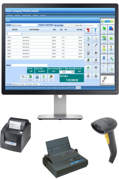
QuickBill is a business solution for small, midsize and large business operation from a single store to a large chain. It is scalable and complete solution for businesses at any stage. It provides greater control over the Inventory, POS / Trading operations along with financials. It's really quick in implementing and is simple, yet comprehensive to use with the power to support your growth plans.
The VCC pins on the digital ports are completely isolated from the Arduino's regulator. Power to the digital VCC rail must be supplied through the external screw terminals. How to Connect External Power for Servos
Additional serial interface for universal UART communications. 2. Power Management and External Supplies
Solution: Verify that no other device on the shield is also trying to use the same SPI lines. Always set the CS pin for your SD card or SPI device as an output and pull it low ( digitalWrite(CS, LOW) ) before any SPI transaction. Check that you are not accidentally using D10 for anything else when the SD interface is active. arduino sensor shield v5 0 manual
: I2C, SPI, UART (Serial), Bluetooth, APC220, and SD Card 🗺️ Board Layout and Pinout Breakdown
: The SEL jumper is still attached. Remove it and connect an external power supply to the screw terminals. The VCC pins on the digital ports are
A multi-pin breakout block tailored for standard SPI-based SD card reader modules.
Note: The grounds of the external power supply and the Arduino remain automatically connected through the shield's internal circuitry to ensure a common reference point. 3. Step-by-Step Connection Examples Scenario A: Connecting a Standard Servo Motor Check that you are not accidentally using D10
Tailored for quick connections to I2C-enabled 16x2 or 20x4 LCD characters screens.
Plug the servo connector directly into the servo headers. The standard servo connector color convention is Brown/Black (GND), Red (VCC), and Yellow/Orange (Signal). 5. Typical Applications Arduino Sensor Shield V5.0 is used to quickly build: Robotic Arms (using the servo headers).
I2C (IIC), Bluetooth, SD Card, APC220 Wireless, and Serial (UART). Mechanical: Laminated design with PCB immersion gold processing. Key Hardware Features 1. Digital and Analog I/O Blocks The shield breaks out all digital pins ( ) and analog pins ( ) into 3-pin clusters. Top Pin (G): Middle Pin (V): positive 5 cap V by default). Bottom Pin (S): Signal (data transfer). 2. External Power Management (SEL Jumper)